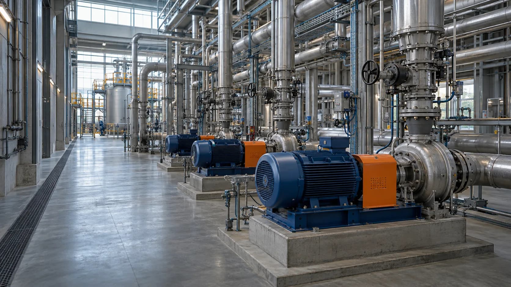
Aging pumps were forcing the facility to run around hydraulic imbalance, increasing energy draw and creating maintenance windows that interrupted production.
Chemical Processing · Rotterdam, Netherlands
Rotterdam Processing Facility
A custom pumping modernization restored hydraulic balance across a major processing facility while reducing maintenance exposure.
Engineering breakdown
Hydraulic balance restored for continuous production.
Axiom mapped the existing duty cycle, selected an AF-P900 train, optimized the system curve, integrated VFD control, and supported staged commissioning around live production.
A tuned system curve, VFD control, and staged commissioning sequence connected pump selection to the live production constraints.
28% energy reduction · 41% lower maintenance cost · 99.6% system availability
28%Energy reduction
41%Lower maintenance cost
99.6%System availability
Portfolio disclosure. The outcomes above are illustrative scenario references, not verified customer or business results.
System visual / illustrative
Three decisions held the upgrade together.
The duty cycle, system curve, and commissioning window shaped the pump-train decision around live production.
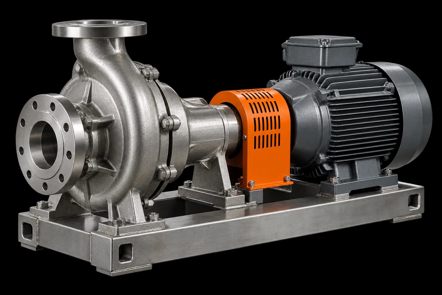 AF-P900 / SYSTEM VIEW
- 01
Map the duty and system curve
Map the operating envelope before selecting the pump train so the equipment decision stays tied to the process.
- 02
Integrate variable-speed control
Evaluate VFD control against the operating profile and the response the process actually needs.
- 03
Commission in stages around live production
Use staged checks, readings, and handoff records to keep the intervention aligned with live production windows.
Conceptual data view
System curve / pump curve
Conceptual only: the intersection illustrates how duty, pump selection, and control intent are reviewed together. It is not a measured performance curve.
Visual note. The system path and curve are conceptual and not to scale; use approved project data for any real selection.